| OWRESET | Example |
OWRESET Pin {, ByteVar}
Function
Generates a 1-Wire reset sequence on Pin, returning (optional) status
information in ByteVar.
Quick Facts
| All SX Models | |
| Special Notes | The DQ pin (specified by Pin) must have a 4.7 kΩ pull-up resister. |
| 1-Wire commands require a FREQ setting of 4 MHz or higher. | |
| Status value | 0 = Bus shorted to Vss; 1 = Bad connection; 2 = Good connection; 3 = No device |
Explanation
All transactions on the 1-Wire bus begin with an Initialization sequence that
consists of a Reset pulse generated by the master, followed by a Presence
pulse generated by the 1-Wire slave. The OWRESET instruction generates
the 1-Wire Reset pulse on the specified DQ Pin and, if ByteVar
is specified, will monitor the bus and return status information to the program.
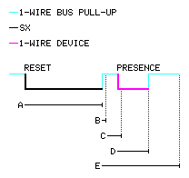
The diagram and table below details the Reset pulse generated by the SX with OWRESET and a typical Presence pulse generated by a 1-Wire slave, in response.
| Note | Timing | Description |
| A | ~ 480 µS | 1-Wire Reset pulse (SX master) |
| B | ~ 15 µS | Delay before sampling for bus short |
| C | ~ 70 µS | Delay before sampling for Presence |
| D | ~ 60 - 240 µS | Presence pulse (1-Wire slave) |
| E | ~ 480 µS | Reset recovery |
Related instructions: OWRDBIT, OWRDBYTE, OWWRBIT, and OWWRBYTE